Some readers may recall my old security door lock, which I made about a year ago. It was controlled with just a single AVR, which proved very inflexible. Though in theory it was capable, it was very limited unless I spent a lot of time and effort interfacing with an internet connectivity module. While that may have been an interesting challenge, the inflexibility and impracticality of the old system was simply too much for me, and I didn’t have time to maintain it. It was generally too time consuming to dismantle the module and reprogram it as required, and so when it broke (the strings simply snapped!) I decided it wasn’t worth the hassle, and went back to a good old-fashioned regular lock.
But, where’s the fun in that? Fast-forward a year to 2014, and I finally convinced myself to buy a Raspberry Pi to mess around with. I already have quite a bit of experience with Linux, so I wasn’t planning to use it to learn Linux. In fact, I didn’t know what I’d use it for until the night before it arrived when it hit me: I could use it to make a much better door lock! And so when it arrived, along with a servo I happened to order with it, I got to work. Here’s the end result:
At the start of the video, you see the Raspberry Pi on the left, the servo/circuit housing in the middle, and the lock itself on the right. In the second half, you can see the keypad connected via a ribbon cable to the circuit housing.
Features:
- Keypad code locking/unlocking
- Web interface to control and view status from any internet connected device
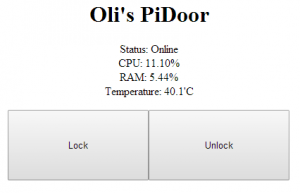
- Easy to update (thanks to the Raspberry Pi itself being a Linux device)
- Mains powered with a single 5v power source
- GPIO ribbon cable/socket for easy removal of the Raspberry Pi
Read on to find out how it works.
The RPi (Raspberry Pi) controls everything. It receives power via the GPIO header, meaning the servo and the RPi can share a single power source. It’s also connected to my home WiFi network via a WiFi dongle. The RPi runs a Python script which listens for UDP data from a specific server IP, and interfaces with the keypad to listen for physical input. If the key combination is correct or the UDP data is correct, then the door lock can be controlled.
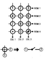
The keypad is a simple £3 matrix keypad. Hook up the columns to RPi outputs, and rows to inputs. Set a column to high, and then look for input on all of the four rows. If a given row is high, you know the column and row of the key pressed and can infer the number pressed.
The lock is controlled with some string and a non-continual rotation servo (which simply means a PWM duty cycle input to the servo corresponds to a target angle)
The servo/circuit housing connects the RPi to the servo, keypad, and power. You can see the GPIO header is connected via a ribbon cable to the circuit housing, where it’s plugged into a socket mounted onto some stripboard inside there. The circuit housing is connected to a 5.0v USB mains power adapter (phone charger!), which then feeds the servo and the RPi (via the GPIO) with power, making one neat mains power connection.
Leave a Reply