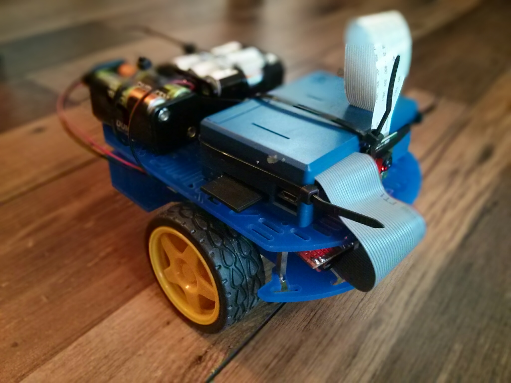
Radio controlled toy cars don’t normally have a Raspberry Pi, 10 batteries and a stripboard loosely hanging off them, but this isn’t your standard RC car.
The primary goal of ICC was to enable a toy car (which has now become a robot, as seen in the image above) to be controlled in real-time over the internet. I did just that, and you can try it out right now!
Come and drive my Internet-Controlled Car: http://projects.bitnode.co.uk/ICC/
Read on for a technical write-up of how I completed the project.
The Beginning
I didn’t want to create my own chassis since the job I could do would have been far less robust than using some pre-existing model as a base. So, I opted for modifying something that already existed. The only toy car I had lying around wasn’t exactly anything special – just a radio controlled car I was given for a present when I was about 9. It has 2 DC motors – 1 for forwards/backwards drive of the rear wheels, and 1 for controlling the steering direction of the front wheels. The steering motor never makes full rotations, and just simply pushes a pinion which drives a rack connected to the steering mechanism. In short: it’s quick and simple, and that makes it very simple for us. This is no longer the case. Instead, I’m using a Dagu robot chassis, as pictured above.
So, the aim was to modify this car in such a way so as to allow it to be controlled remotely over the internet. Actually, that isn’t quite true. I wanted it to be controlled by any number of people on the internet (one at a time, of course – responsible driving). I set out a rough specification, and got to work.
Specification
I set out a list of requirements for the end result:
- The car should be able to be controlled over the internet
- Quite key
- The car should be totally wireless
- WiFi is the obvious choice for this
- The car should be controlled from a webpage which allows a queue of users
- If this is to work for any number of users and not just myself, then this is required
- The car should have a mounted camera to allow the user to see where they’re driving
- Obvious, but difficult to actually get right, as we’ll see…
The above can all be achieved using a single Raspberry Pi running from batteries with a WiFi dongle, a camera module, and some external motor control circuitry. Here’s a pretty diagram:
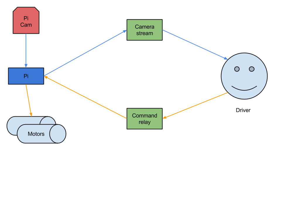
Now to make it happen…
Camera and visual display
So, the users need to see where they’re going. What I learned from the last time I tried this experiment was that this is quite hard to get right. With this in mind, I got to work on this aspect first before moving on with the rest of the project.
Last time I approached this problem, I went down the easy route: I mounted my phone on a table and used the Ustream app to broadcast a live feed of the room. That was a disaster. Not only was it apparently deceptively difficult to control the car from a fixed location, but the Ustream service added in about 10 seconds of delay. That meant my poor users were driving practically blind, and could only see that they were running into my cat and driving up my chimney 10 seconds after the fact (though I still have a sneaking suspicion that some of that was on purpose). It was easy to get up and running, but Ustream really isn’t designed for this type of streaming.
So, this time I tried something new. I was already planning on using a Raspberry Pi to facilitate easy WiFi connectivity, so I opted for a Raspberry Pi camera module. I was extremely impressed by the camera module – it was incredibly easy to set up and get going. Now I just needed to get a live stream of the camera over the internet. ‘Just’.
Firstly, I tried VLC. VLC is great, and its streaming capabilities were a piece of cake to use. Unfortunately, I couldn’t find anything to play the stream types it provided in a browser (though it worked well from VLC server to the VLC client!). So that was out of the window, since I wanted to be able to embed the stream directly in the webpage. Next I tried FFmpeg. Also another brilliant piece of software, seemingly ruined by the Libav/avserver software, which is a fork of FFmpeg. Maybe that’s an unfair/sour judgement, but Libav didn’t work on my Pi (it would crash shortly after starting the stream), and the server/relay aspect, avserver, would simply crash as soon as it started up. So, after much faffing, cross compiling, and configuration, I got FFmpeg setup and working instead. Except my Pi couldn’t handle encoding things like FLV streams (due to a lack of processing power), and FFmpeg’s MJPEG streaming is seemingly broken too. Even when FFmpeg worked, it introduced an unacceptable delay on the stream, which as I mentioned previously, is only good if you’re okay with terrified cats and sooty cars.
Disgruntled, frustrated and possibly slightly sleep deprived, I couldn’t think of another way to continue with VLC or FFmpeg, despite many more hours of debugging, and I decided to give up on that approach. I’m 99% certain there’s some way to force the FFmpeg server to do the transcoding and for the FFmpeg client on the Pi to just send raw data, but I was tired of endless bugs and strange errors. I just wanted a simple image stream from my Pi, which I could then relay to N clients. I didn’t really care about the fancy stuff FFmpeg and the likes could do, because this project doesn’t really need them. Fortunately, I stumbled across a fork of mjpeg-streamer, which is a nifty bit of software designed to create an MJPEG stream from the Raspberry Pi camera. It all built easily and worked very reliably with minimal setup and minimal resource usage. I can’t recommend it highly enough for these types of projects, so go and give this project a star: https://github.com/jacksonliam/mjpg-streamer.
I decided that, despite its inefficiency, MJPEG was the best approach, since it required very little CPU processing and had a simple format, which became very helpful when I set to work on the next problem: relaying the stream to N clients. One of the original goals of this project was to create a sense of interaction with other users, so I thought it would be fun if not only the driver saw the camera stream, but all the users on the web page (also that way, everyone can judge your driving). However, I didn’t want to burden the Pi (or my home upload speed) with streaming to too many clients, so I decided to try and re-broadcast a single stream from the Pi to N clients. I found an old bit of code online which claimed to relay MJPEG streams, but as was the trend with this project, it didn’t seem to work either. At this point I was prepared to make my own solution, so that’s what I did. I read up on the format of MJPEG (which is very simple!), and I set to work on a Python script which simply connected to the MJPEG stream provided by mjpeg-streamer, and relayed the raw data to connected clients. It’s mostly straightforward, you just have to respect JPEG boundaries of the individual frames in the stream and ensure the clients get the right headers. After that, the streaming is just a case of relaying whatever you get from the MJPEG stream source. The code is here if you’re interested: https://github.com/OliverF/mjpeg-relay.
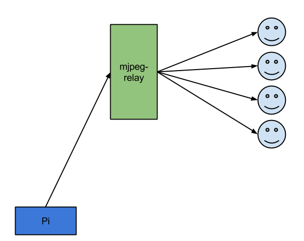
So to summarize:
- mjpeg-streamer acquires the feed from the Raspberry Pi camera module, and makes it available as an MJPEG stream
- mjpeg-relay reads the MJPEG stream and relays it to N connected clients
What’s really nice about the above is that because there is no transcoding, there is very little delay. Even relaying the stream to my VPS in the Netherlands and back again introduces a largely unnoticeable delay. As a bonus, most good browsers support MJPEG embedding directly into a webpage, so no Java applets, JavaScript code, or other workarounds are required.
Hardware
The camera was set up and working happily, now I had to make the Pi control the motors. The general approach was to use a H-bridge motor controller IC to control the two DC motors within the car.
Power considerations
- The Pi model B draws about 500mA.
- The camera modules draws about 250mA.
- The WiFi dongle draws another 250mA.
This totals up to roughly 1A, and that’s not even considering the motors. In my design, I designed the power supply for the Pi/motor controllers to be separate from the motor power supply. You can just use a single power supply, but watch out for back-EMF.
So that I didn’t burn through the world’s supply of AA batteries in a single day, I opted for rechargeable NiMh AA batteries. 6 for the Pi/ICs, 4 for the motors (since the car was originally designed to power the motors with 4 batteries and this way I only needed one voltage regulator for the Pi/ICs).
Design
One thing I noticed while designing this stage was that there seems to be no formal way of representing a stripboard layout. I ended up with a rather cheesy looking yet understandable layout, shown below. The layout was made using made using DIYLC, a prototype layout tool.

- The block on the right is the 26 pin GPIO header, which is used to connect to the Pi (header, cable).
- Q1 is a 1.5A, 5V fixed voltage self-contained switching regulator module (datasheet).
- This regulator allows us to use a battery pack of >4 1.2V batteries (remember, rechargeable NiMh batteries are 1.2v), while still providing the 5V required by the Pi and motor controller ICs.
- Note: 4 perfect 1.2V batteries would provide the 5V required by the Pi, but never connect batteries to the Pi directly in that manner – always use a regulator as shown in the layout above. Even NiMh batteries which state 1.2V on the side will produce ~1.4V each when fully charged, so using 4×1.4V = 5.6V may at worst damage/kill your Pi, and at least just simply become unstable after the batteries begin to drain.
- As previously mentioned, the system draws ~1A. To play on the safe side, I used a 1.5A regulator.
- IC1/IC2 are H-Bridge motor controllers (datasheet).
- This allows a motor to be driven in either direction, depending on the logic levels of 3 inputs. The details are specified in the datasheet.
- There is only 1 enable pin on each IC, so you can’t run the drive motors without also powering the steering, and vice versa.
- You could choose a different motor controller perhaps with 2 separate enable pins – I just happened to have these.
- My design includes 2 separate power supplies, one for the motors and one for the Pi and motor controllers. The supply for the ICs and Pi is regulated, while the motor supply is connected directly.
- You can just use a single power source, but watch out for back-EMF.
I soldered it all up, and connected the car’s motors to the stripboard. To my surprise, it all worked first time!
An aside: linear regulators
I initially opted for the use of a linear regulator for Q1, but I discovered that it was getting too hot during usage. It was dissipating about 4V at 1A = 4W, which according to its datasheet, should have pushed the temperature of the regulator up to 200C. Oops. I switched it out for a direct “drop in replacement” pre-built switching regulator module (linked above), which has a much greater efficiency, thereby reducing the heat of the regulator while conserving battery life.
Motor control
The hardware and visuals were ready, now I just had to control the motors from the Pi. Using the datasheet for the H-bridge motor controllers, it was just a simple case of setting the right outputs depending on the direction/action required. The code can be found here: https://gist.github.com/OliverF/f0a75ed4dd38c029b779.
Front end
The front end is made entirely in JavaScript. It connects using WebSockets to a node.js server, which then relays commands via TCP to the Pi. The node.js server handles the user queue to ensure only one user can control the car at a time. The code can be found here: https://gist.github.com/OliverF/ddc88eae83675ae3aac4.
Leave a Reply